Braun Karl Ferdinand biography
Date of birth : 1850-06-06
Date of death : 1918-04-20
Birthplace : Fulda, Germany
Nationality : German
Category : Science and Technology
Last modified : 2010-05-31
Credited as : Physicist, Nobel Prize for Physics, crystal radio detectors in wireless telegraphy
0 votes so far
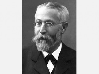
He shared the Nobel Prize for physics in 1909 with Guglielmo Marconi for his contributions to the development of wireless telegraphy. Braun is also known as the developer of the cathode ray oscilloscope, the precursor to the radar screen and the television tube. Braun’s family house in Fulda.
Karl Ferdinand Braun was born on June 6, 1850 in the German city of Fulda. Not surprisingly, early in his life Ferdinand Braun demonstrated that he was a diligent student with a strong talent for science. Before he finished his “Gymnasium” (high school) studies, several journals had published scientific articles by the young man.
Initially intending to be a gymnasium science teacher, Braun began a general science and mathematics curriculum at the University of Marburg. Soon, however, he transferred to the University of Berlin where he focused his studies on physics and ultimately was awarded a Ph.D. in 1872.
Braun’s first investigations were concerned with oscillations of strings and elastic rods, especially with regard to the influence of the amplitude and environment of rods on their oscillations. Other studies were based on thermodynamic principles, such as those on the influence of pressure on the solubility of solids.
He worked as assistant to Professor Quincke at Wurzburg University and in 1874 accepted a teaching appointment to the St. Thomas Gymnasium in Leipzig. Two years later he was appointed Extraordinary Professor of Theoretical Physics at the University of Marburg, and in 1880 he was invited to fill a similar post at Strasbourg University.
Braun was made Professor of Physics at the Technische Hochschule in Karlsruhe in 1883 and was finally invited by the University of Tubingen in 1885; one of his tasks there was to build a new Physics Institute. Ten years later, in 1895, he returned to Strasbourg as Principal of the Physics Institute, where he remained, in spite of an invitation from Leipzig University to succeed G. Wiedemann.
Karl Ferdinand Braun and his wife Amelie Buhler, 23 May, 1885
His most important works were in the field of electricity. He published papers on deviations from Ohm’s law and on the calculations of the electromotive force of reversible galvanic elements from thermal sources.
Braun’s interest in the electrical conductivity of metal salts in solution (electrolytes) ultimately led to his study of metal sulfide crystals and other crystalline solids which conduct even when not dissolved. After much experimentation, Braun reported in 1874 that for many metal sulfides the electrical resistance varies with the magnitude and polarity of the applied voltage.
He used the rectifying properties of the galena crystal, a semiconductor material composed of lead sulfide, to create the cat’s whisker diode for this purpose. He found this phenomenon to be especially true if at least one of the electrodes was a pointed wire. In other words, Ferdinand Braun had discovered the point-contact rectifier effect. Thus was born the first semiconductor device.
This effect had no practical application at the time but would be rediscovered over thirty years later in the form of the “cat’s whisker” crystal radio detector and would be instrumental in the point-contact transistor first produced in 1948.
The next twenty-odd years of Braun’s life were occupied with university teaching and physics research, most of which involved some aspect of electricity. During this period, he developed several electrical measurement instruments of importance to the physicists of that day. His next contribution of truly lasting significance, however, did not come until 1897. His practical experiments led him to invent what is now called Braun’s electrometer, and also a cathode-ray oscillograph, constructed in 1897.
The existence of electrons (“cathode rays”) had been established that year and X-rays had been discovered only two years earlier. Both were of great interest to Ferdinand Braun. It was known that if high voltage were applied between two electrodes in an evacuated (low pressure) glass tube, electrons were emitted from the cathode and traveled to the anode.
It also was known that certain materials would luminesce when struck by the electrons. This information was all Braun needed in 1897 to build what he called his “cathode ray indicator tube.” (The term “cathode ray tube” without the word “indicator” included was often used in those days to refer to any evacuated tube used for studying the effects of cathode rays.).
Numerous phenomena characterized by oscillatory electric voltages and currents were becoming increasingly important to physicists. Electromechanical oscillographs, using tiny mirrors to project a beam of light on a screen, existed which could display the waveforms of the 50 or 60 Hz voltages produced by power stations. However, these instruments were not able to function at higher frequencies.
This is an actual Braun Cathode Ray Tube. Braun developed this tube at the University of Strassbourg starting in 1897. This is a cold cathode tube with only about one third of the electrons passing through a hole in the aluminum plate (between the anode and phosphor screen) and striking the phosphor screen. It requires 10,000 to 20,000 volts between the cathode and anode to operate.
In 1897, on February 15th, Ferdinand Braun published in the journal “Annalen der Physik und Chemie” his research results on a method to record and study the time dependance of alternating currents (“ein Verfahren zur Demonstration und zum Studium des zeitlichen Verlaufs variabler Strome”).
He invented and developed the so-called “Braun tube” as a fast responding recording instrument, the first cathode-ray oscilloscope. Cathode-ray tubes had previously been characterized by uncontrolled rays; Braun succeeded in producing a narrow stream of electrons, guided by means of alternating voltage, that could trace patterns on a fluorescent screen.
In Braun’s original cathode ray tube (CRT), the oscillatory electrical current to be observed flowed through a coil wrapped around the discharge tube. This resulted in a vertical deflection of the electron beam. The amount of vertical deflection was proportional to the intensity of the oscillatory signal being measured. The trace on the face of Braun’s CRT was merely a vertical line.
What we today would call “horizontal deflection” of the image to create a “time” axis was achieved by means of a small rapidly rotating mirror placed in front of the CRT.
Electrostatic horizontal deflection of the electron beam was first achieved by one of Braun’s assistants some thirteen years later. Characteristic of Braun’s attitude toward scientific discovery, he never patented his cathode ray indicator tube. Rather, he published a detailed description of how his tube was constructed so that any scientist could build one. This invention, the forerunner of the television tube and radarscope, also became an important laboratory research instrument.
Cathode-ray oscilloscope electronic display device containing a cathode-ray tube (CRT), used to produce visible patterns that are the graphical representations of electrical signals. The graphs plot the relationships between two or more variables, with the horizontal axis normally being a function of time and the vertical axis usually a function of the voltage generated by the input signal to the oscilloscope.
Because almost any physical phenomenon can be converted into a corresponding electric voltage, with the use of a transducer, the oscilloscope is a versatile tool in all forms of physical investigation. The German physicist Ferdinand Braun developed the first cathode-ray oscilloscope in 1897.
Speed of response is the cathode-ray oscilloscope’s chief advantage over other plotting devices. General-purpose oscilloscopes have plotting frequencies of up to 100 megahertz (MHz). Response times as rapid as 2,000 MHz are achievable with special-purpose, high-speed oscilloscopes.
The central component in this device, the cathode-ray tube, consists of an evacuated glass container with a phosphorescent coating at one end (similar to that of a television screen) and an electron gun and system for focusing and deflecting the beam of electrons at the other. The electron beam emerging from the electron gun passes between pairs of metal plates mounted in such a way that they deflect the beam horizontally and vertically to control the production of a luminous pattern on the screen.
The screen image is a visual representation of the voltages applied to the deflection plates. Alternatively, the beam may be deflected magnetically by varying the currents through externally mounted deflection coils. Thus, almost any graph can be plotted on the screen by generating horizontal and vertical deflection voltages or currents proportional to the lengths, velocities, or other quantities being observed.
It is sometimes necessary or desirable to plot more than one waveform at the same time on the screen of an oscilloscope. Using a variety of techniques, four or more plots can be simultaneously shown. With a dual-trace amplifier and a single CRT gun, two signals may be shown at what appears to be the same time.
Actually, the amplifier electronically switches rapidly between the two observed signals. In a split-beam CRT the electron beam from a single gun is split, with the two parts receiving different vertical deflections. A dual-gun CRT uses two separate electron guns, each having its own focus and brightness controls. By combining two dual-trace amplifiers with a dual-gun CRT, four individual plots can be obtained.
The cathode-ray oscilloscope is one of the most widely used test instruments; its commercial, engineering, and scientific applications include acoustic research, television-production engineering, and electronics design.
Ferdinand Braun became involved with wireless telegraphy early in 1898. He had been hired by Ludwig Stollwerck to explain the technical principles behind a working system for underwater wireless telegraphy, which had been developed by three scientifically untrained men. It also was hoped that Braun would be able to suggest ways to increase the range of the telegraphy system.
Stollwerck was a highly successful Cologne candy maker who had been approached to provide the money needed to develop and market the underwater communication system. In the course of making himself familiar with the then-existing state of wireless telegraphy, Braun soon became aware of the work of Lodge, Slaby, Marconi, and others. Braun was interested in determining why both Marconi and Slaby were finding it difficult to increase the distances over which their transmissions could be received.
The approach both had used involved increasing the voltage (and, hence, energy) of the spark transmitter discharges. However, large increases in the spark voltage resulted in only small increases in the distances spanned. Although Marconi had transmitted as far as 50 km, success beyond 15 km required disproportionately larger amounts of electrical energy.
Ferdinand Braun studied the design of Marconi’s transmitter, which had the spark gap connected directly between the antenna and ground. Braun remembered that, to increase the range of the underwater telegraphy system, he (Braun) had changed the original circuit which also had the antenna directly coupled to the spark discharge. In Braun’s improved arrangement, a primary coil was placed in the oscillation producing spark gap circuit. That coil and a loosely coupled secondary coil were used to transfer energy to the antenna. The effective communication range of the underwater system had increased even more when both the oscillator circuit and the antenna circuit were in resonance.
Direct coupling (also called “tight” coupling) of the antenna to the oscillator resulted in the production of bursts or pulses of highly damped oscillations. Much energy was dissipated in circuit losses. The highly damped pulses of oscillations were not effective for long distance communicating.
The radiated energy was spread over a wide range of frequencies resulting in interference to other stations due to the inability to tune receivers to a particular frequency. Direct coupling of the antenna was limiting the range of Marconi’s transmitter.
The “loose” coupling, which Braun now used between the spark-gap oscillator circuit and the antenna circuit, produced considerably less damping of the pulses of oscillations. The effect of low damping was highly beneficial in that much more energy was radiated and the energy was distributed over a much narrower range of frequencies. Making the two circuits resonant further increased the amount of energy transferred to the antenna.
The range of the underwater wireless telegraphy system still was limited to relatively short distances due to other factors. However, Braun’s use of loose coupling between the oscillator and antenna circuits of a conventional wireless transmitter now dramatically increased the range of aerial (i.e., through air) transmissions. This was demonstrated by Braun in a hastily improvised test on September 20, 1898.
Within a month of his initial test, the normally conservative Braun predicted that his aerial wireless telegraphy equipment now would be able to span distances of 100 km. Stollwerck and his partners who wanted to form a corporation for developing and marketing wireless telegraphy equipment for military and commercial applications were jubilant. Braun’s improvements effectively eliminated Marconi’s previous patent monopoly on wireless telegraphy.
The new company, which would be known as “Telebraun,” was formed and the company filed an application for a patent on Braun’s circuit. (After several subsequent mergers and name changes, the company with which Braun was associated would be called “Telefunken.”).
Braun experimented with wireless telegraphy and succeeded to establish the first wireless communication over greater distances. The first wireless telegram was sent over a long distance (62 km) on Sept. 1900, from Helgoland to Cuxhaven:
Braun knew that having an improved receiver also was critically important to achieving a truly commercially successful system of wireless telegraphy. As did many others, Braun realized that the coherer detector was, at best, temperamental and unreliable.
In 1899, he tried to utilize the crystal rectifier effect, which he had first discovered in 1874. Braun found that the crystal detector provided no improvement over the coherer when the wireless telegraphy messages were automatically recorded on a moving strip of paper, as was the normal practice at the time.
By 1901, the advantages of having a human telegraph operator decipher and manually record the messages were recognized. Then Braun’s crystal detector was found to be superior to the coherer. However, when transmitters which produced continuous, undamped oscillations became available, neither the coherer nor Braun’s crystal detector could produce an audible response. Braun’s crystal detector, however, was “rediscovered” and improved in a few years by others for use as an inexpensive and reasonably reliable detector for radiotelephony.
Braun reasoned that if loose coupling between the oscillator and antenna benefitted the performance of the transmitter, it might also improve the performance of the receiver. In 1902, he carried out experiments which demonstrated that transferring energy from the receiving antenna to the detector through two loosely coupled coils resulted in both a sharper resonance effect as well as increased received signal strength.
The benefits to reliable long distance communication which resonance at both the transmitter and receiver provided were obvious to all who were seeking to develop wireless telegraphy. Marconi had been trying to achieve the same result. Everyone, especially Marconi, knew that the person who held the strongest patent on tuning would accrue great financial rewards.
Marconi filed an application for what would become known as his “four-sevens” tuning patent for transmitters on April 26, 1900. Braun felt that Marconi’s was very similar to the first part of Braun’s own British patent on tuning which had been filed on January 26, 1899. In addition, Braun also felt that subsequent tuning patent applications filed by Marconi in 1901 were remarkably similar to the second part of his (Braun’s) British patent.
Braun reported that, when the two men later discussed the matter, Marconi admitted with “commendable frankness” that he had “borrowed” Braun’s ideas. For some unexplained reason, Braun-Siemens (the new name of the company with which Braun was associated) did not immediately sue Marconi. When a suit was filed later, the company found that its delay had severely weakened its legal position.
Being able to tune the transmitter and receiver helped provide privacy in communications as well as greater communication range. This was very important to both military and commercial users of wireless. In 1901, Braun sought to increase both the privacy and range even more with the development of directional antennas.
One of Braun’s first findings was that a moderate amount of directivity in receiving could be achieved if the antenna was inclined slightly (less than ten degrees) to the horizon. Reception was best for waves that passed through the vertical plane containing the antenna. Achieving directivity in transmitting antennas was somewhat more complicated.
Braun first tried to replicate the action of the parabolic mirror in a searchlight by using an array of vertical antenna wires mounted on poles arranged to form a cylindrical parabola. By properly adjusting the phase of the signal applied to each wire, it would be possible (in principle) to produce a direction of maximum electromagnetic wave intensity. Achieving the desired results in practice, however, is very difficult with an antenna configuration of practical size.
Braun’s results were unsatisfactory. Braun then reduced the number of antenna wires and poles to three and was able to excite the wires from a common transmitter by arranging the poles in an equilateral triangular pattern. By carefully controlling the relative phases of the transmitter currents in the three wires, significant directivity of the radiated signal was achieved by Braun and his assistants.
Braun’s papers on wireless telegraphy were published in 1901 in the form of a brochure under the title “Drahtlose Telegraphie durch Wasser und Luff” (Wireless telegraphy through water and air).
In 1909, the future importance of the CRT was not at all clear to the Nobel Prize Committee members. What was clear, however, was that wireless telegraphy already was profoundly changing the way the world communicated.
It was for this reason that the Nobel Prize Committee recognized the separate, but equally important, complementary wireless telegraphy achievements of Braun and Marconi. While Marconi’s accomplishments were more spectacular and much more highly publicized, Braun’s achievements were no less important to the overall development of wireless telegraphy.
In the minds of many, Karl Ferdinand Braun’s contributions to the development of wireless telegraphy are obscured by those of Marconi. The reason for this largely is due to the personality differences between the two men. Unlike Marconi, Braun avoided publicity and sought no personal recognition for his work. Braun saw his work solely in terms of helping advancement of science.
The significance of Braun’s work, however, must not be underestimated. That significance is best summarized by the following remarks by H. Hildebrand, President of the Royal Swedish Academy of Sciences, in the presentation speech made prior to the joint awarding of the 1909 Nobel Prize in Physics to Braun and Marconi:
“Marconi’s original system had its weak points. The electrical oscillations sent out from the transmitting station were relatively weak and consisted of wave-series following each other, of which the amplitude rapidly fell – so-called “damped oscillations.” A result of this was that the waves had a very weak effect at the receiving station, with the further result that waves from various other transmitting stations readily interfered, thus acting disturbing (sic) at the receiving station.
It is due above all to the inspired work of Professor Ferdinand Braun that this unsatisfactory state of affairs was overcome. Braun made a modification in the layout of the circuit for the dispatch of electrical waves so that it was possible to produce intense waves with very little damping.
It was only through this that the so-called “long distance telegraphy” became possible, where the oscillations from the transmitting station, as a result of resonance, could exert the maximum possible effect upon the receiving station. The further advantage was obtained that in the main only waves of the frequency used by the transmitting station were effective at the receiving station. It is only through the introduction of these improvements that the magnificent results in the use of wireless telegraphy have been attained in recent times.”
Shortly after World War I began in Europe, Braun came to the United States to testify in a patent dispute. The subsequent involvement of the United States in that war, together with an incurable illness, made it impossible for Braun to return to Germany.
He lived at his son’s home in Brooklyn, NY until his death.
After heavy suffering Professor Ferdinand Braun passed away the morning of the 20th of April, 1918. Later he was buried in his home-town Fulda, Germany.
Karl Ferdinand Braun and Guglielmo Marconi were memorized in a special stamp dedicated to their Nobel Prize “in recognition of their contributions to the development of wireless telegraphy.”


